| 351C
4V Cam Change: Installation |

19 Changing a cam is a back breaking chore, especially
on a lowered car. But we're confident it will be all worth
it with the around town drivability we'll achieve. |

20 With the old cam and lifters removed, we spent
some time cleaning off all the old gasket material, and
using a shop vac to suck up and crud, coolant, and old
silicone from the intake valley. |

21 It's always wise to clean new cams with solvent
and blow dry with compressed air, to ensure any machining
oils and grit are removed. |

22 Looking at the two cams side by side, the differences
are apparent. Note the steep and narrow profile of the
Ultradyne cam (right) compared to the less aggressive
lobe profile of the Crane cam. |

23 Using a long bolt to help support the cam, we
slid the cam in to the first bearing, then applied the
Crane moly lube generously on the camshaft lobes while
slowly guiding the camshaft into the bore. The cam retaining
plate is then reattached. |

24 Similarly, the lifters were coated with moly
lube and carefully placed into their bores. There is no
need to soak them in oil to "pump them up" prior
to assembly. |

25 Since we were installing the cam "straight
up" with no advance or retard, we opted not to degree
the camshaft. Whether you've got a timing chain or gear
set, the cam timing procedure is the same. Line up the
index dot on the cam sprocket with the key on the crank
so they are 6 o'clock and 12 o'clock respectively. This
is now top dead center (TDC) on the power stroke for cylinder
1. |

26 The original timing cover had developed serious
pitting and corrosion. Unfortunately we didn't give this
serious concern and put it back on the motor. While filling
the radiator with coolant we noticed coolant dripping
at a very fast rate below the water pump. |

27 The timing cover was cleaned thoroughly, especially
the front pan seal groove. |

28 Fortunately we had a spare 351C motor in our
possession, and the timing cover was in much better shape.
We cleaned it up and stayed up late into the night swapping
it out -regretting not doing so the first time around. |
|

29 We applied a thin smear of RTV around the
water passages on both sides of the timing cover and
waterpump gaskets.
|

30 The timing cover gasket is carefully placed
over the dowel pins. |

31 After some struggling trying to get the timing
cover over the dowel pins without disturbing the front
seal, we decided the only way to ensure a leak free installation
would be to lower the pan slightly. On the Torino the
pan bolts are not hard to get too, and fortunately the
cork gasket was in good shape and let the pan down with
out any fuss. |

32 The timing cover is carefully set in place,
and the timing pointer / bracket is secured. |

33 The waterpump bolts are tightened evenly, ensuring
a leak free seal. It's a good idea to wait about 20-30
minutes before filling the system with coolant, to allow
the RTV sealant to set. |

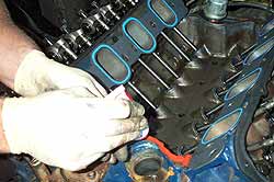
34 Before bolting the intake back in place, we
dropped in the pushrods, and set the rocker arms on the
studs, with the adjusting nuts just one turn at this point
until we set the lifter preload. |

35 Setting lifter preload on hydraulic rockers
is simple. Starting with the crank set at TDC for cylinder
#1, we'll rotate the crank by hand and watch for the exhaust
lifter to just come off the base circle. As the exhaust
lifter begins to move up, off the base circle, stop and
set the preload on the intake side. Then continue rotating
the crank, while watching the intake lifter. The lifter
will rise completely and then begin to decend back down
the bore, when it is just about all the way down, stop
and adjust the exhaust rocker. |

36 Preload is set by tightening the rocker adjusting
nut until all the slack is just taken up from the push
rod (use your free hand to spin the push rod and move
it up and down until the slack is just taken up, it
is important not to go beyond this point.) Then give
the nut another 1/2 to 3/4 of one turn, which will set
the lifter plunger preload between 0.20"
to 0.60". Finally, secure the allen-head lock
screw against the stud, using a wrench to prevent additional
turning of the adjusting nut.
View
more detailed instructions for setting preload.
|

37 After all the rocker arms are adjusted, the
intake is replaced. We're using Fel Pro Printoseal intake
manifold gaskets. Rather than using the supplied cork
end seals, we recommend using a thick bead of RTV silicone,
it provides a better seal and no chance of the cork slipping
out of place. |

38 We decided to use the Torker single plane intake
manifold which we had been running. Admittedly a simgle
plane is not the ideal manifold type with this mild cam.
At some point we will consider obtaining a dual plane
intake to replace it. Torque the bolts in a criss-cross
pattern to 20 lb.ft. |
 |
39
After bolting the carb and distributor back up,
the fluids were replaced as well as the oil filter.
The cam and lifters were broken in by running
the motor between 2000-3000 rpm for 15 minutes.
Initial test drives confirm the dramatic change
in driveability. Idle is much smoother, and the
motor does not surge at low speeds. The new powerband
will also better suit the cars 3.50 rear end and
2500 rpm stall converter. 
|
Contacts:
Crane Cams, Inc.
http://www.cranecams.com
530 Fentress Blvd.
Daytona Beach, FL 32114
386-258-6174 Tech Line
|

