 Place some RTV sealant o nthe saddle and main cap
mating surface, adjacent to the rear main seal groove.
This will help prevent the dreaded rear-main leak.
 |
|

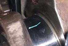
 We've placed a small strip of Plastigauge™
on the main bearing crank surface in order to measure
clearances. Refer to our "Measuring
Bearing Clearances" article in the Fundamentals
section.
 |
| |
|
|

 Install the ARP washers and nuts using the supplied
moly lubricant on the threads. Oil may also be used
however pay close attention to ARP's torque specifications
depending on the lubricant being used.
|
|

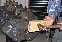
 With the caps snugged but not torqued to specification
we seat the thrust bearing by giving the crank a
few smart smacks with a hammer (wood used to protect
the snout.) Do the same at the back of the crank.
The same can be achieved by prying back and forth
using large screwdriver between main cap #3 and
the crank throw.
 |
| |
|
|

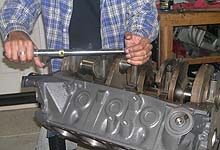
 We torqued the main studs to 90 ft.lbs. based on
ARP's specification for moly lubricant. Do not use
the factory spec's when using non-Ford fasteners.
We also recommend backing off all the nuts then
retorquing two or three times to compensate for
stud stretch.
 |
|

 Our main bearing clearance checked out to 0.002".
Ford factory specifications for big blocks with
the 3.00" journal diameter range from 0.0007"
up to 0.003".
 |
| |
|
|

 With the crankshaft in place we are ready to hang
the rod and piston assemblies. To keep costs down
we are running the stock pistons but upgrading to
a Total Seal gapless ring set (see side bar.)
This will ensure good sealing and compression with
our slightly looser piston and bore.
|
|

 Ring pack assembly begins with first checking for
minimum top ring gap. Place the ring about 1"
down the bore (use a piston upside down to square
the ring). Using a feeler guage to measure the gap.
A naturally aspirated motor should run at least
0.0045" of top ring gap for each 1 inch of
bore. Thus our 460 calculated as: 4.36" x 0.0045"
= 0.020". We measured 0.024" which is
enough to prevent ends butting and subsequent damage.
 |
| |
|
|

 The three piece oil ring set goes into the bottom-most
piston groove, and installs by hand. Use a ring
spreader tool to get the second and top rings in
place. Top ring usually has a dot which installs
facing up. The machined groove in the gapless second
ring faces down.
 |
|

 The Total Seal gapless second
ring consists of a thin "rail" ring which
seats into the machined groove of the iron second
ring. This rail, as with oil ring rails, goes in
carefully by hand. Ensure it is properly seated
in the larger ring.
 |
| |
|
|

 With rod bearing shells loaded,
stagger the rings as indicated in the ring set instructions,
then load into a good quality ring compressor tool.
Set the piston and rod into the cylinder and use
the handle of a hammer to knock the piston into
the bore. Stop if you feel resistance, as this likely
indicates a ring has caught the deck.
 |
|

 Each rod bearing cap is setup
with a Clevite 77 standard size rod bearing. Apply
a coating of moly lubricant to the crank side and
install as each piston/rod assembly goes into the
block.
 |
| |
|
|

 The stock 3/8" rod bolts
will suffice in our less-than-5500 rpm motor. ARP's
Wavelock bolts are the way to go however there is
cost in having the rod ends resized at the machine
shop. Torque to factory specs: 40-45 ft.lbs.
 |
|

 With the bottom end completed we are ready to move
on to the glory end of the motor- heads, cam and
intake. In Part II we'll detail the selection and
installation of the indution components.
  |

