In part
one of this series we introduced you to the concept
of the 302 based stroker. We also began work on our 331
cubic inch stroker engine. The engine will replace the
302 in our '67 Mustang project car (formerly known as
"Project 11.99").
We left off last time having
clearanced the cylinder skirts to prevent interference
with the rod cap-screws due to the increased stroke
of 331 crankshaft. As we detailed previously we have
selected a complete 331 stroker kit from SCAT Crankshafts.
The kit includes 5.400" forged H-beam rods, 3.250"
stroke cast steel crank, and SRP forged flat-top pistons.
We completed the kit with Total Seal rings and Clevite
bearings.
In this article we'll take
you step by step through the assembly of the motor,
and discuss the cam, heads, and intake selection.
| Machine Work
and Engine Assembly |

1. A Sunnen boring
and honing machine completes the over boring and
torque-plate honing of our '89 302 block. |

2. Block is back
from the machine shop with a 4.030" overbore,
decks milled 0.005" and squared to the crank
centerline. |
|

3. Part of the machine
shop work was to install new cam bearings and
freeze plugs. Notice how the oil galley plugs
are "staked" into place to prevent from
coming loose. Alternatively you can tap and install
screw in plugs.
|

4. One of the first
things we after receiving the block back is check
for proper main and rod bearing clearances using
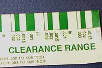
Plastigauge. The green Plastigauge is used for 0.001"-0.003"
range. |

5. The ARP main studs
are screwed, hand tight, into place. |

6. The Clevite main
bearings are installed, dry, for the purposes of
checking clearance. Note the grooved bearings go
into the block saddles. |

7. The
crank is carefully laid into place. Then a strip
of the Plastiguage wax is carefully placed on several
journals. |

8. The non-grooved
bearing halves are set into the main caps. Use a
very light smear of oil on the crank side of the
bearing to prevent the Plastiguage from sticking. |

9.The studs are then
torqued to specification (80 lb.ft. working from
the center outward, and using moly lube on the threads)
|

10. Do NOT rotate
the crank while checking clearances with Plastiguage!
After torquing to spec, remove the nuts and main
caps. Usually a whack on the side of the cap with
a mallet or piece of wood will dislodge a stubborn
cap. |

11. Carefully remove
the main caps, and you are left with a squished
piece of Plastiguage Using the template gradations
on the packaging, you can determine how much clearance
exists. The wider the wax, the less the clearance.
We're at 0.0015" |

12. The same procedure
can be used to measure rod-bearing clearances.
For main bearings 0.001" - 0.002" is
ideal for clearance on a street - strip motor.
For rod bearings aim for 0.001" - 0.0015".
If clearances are out of specification, talk to
your machine shop about cutting the crank down
to use oversize bearings.
|
| |
|
|

