Fitting
the Fan Continued
Now that the trim work was done, it was time to think
about fitting the fan and fabricating some brackets.
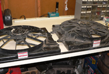
 Here is the "cut" and the spare uncut"
fan side-by-side. Note the difference in depth.
 |
|

 Next, I test fit the fan in the motor compartment.
 |
| |
|
|

 Mounting the fan securely is much easier with the radiator
out of the car.
|
|

 Fortunately, the Mark VIII fan was very appropriately
sized for the
stock radiator. |
| |
|
|

 With some 3/4" angle iron I picked up at Home Depot,
I welded a couple
of L-brackets to the bottom of the radiator. |
|

 After drilling a small mounting hole through the bracket
and into the
lower part of the shroud, I secured the fan with a old
oil pan bolt and a
matching nut. |
| |
|
|

 The top of the fan was secured with a couple long machine
screws and nuts. The factory shroud mounting holes in
the radiator were used.
|
|
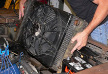
 With the fan secured, I dropped the new fan and radiator
assembly into the core support and got my mind prepared
for wiring in the SPAL controller.
|
| |
|
|
SPAL Fan Controller:
FAN-PWN
Here's the unit I used. The SPAL
FAN-PWM allows a single electric fan to vary speed
based on engine temperature. Low and a high temperature
settings can be set by the user. When the low setting
is reached the fan begins spinning at 50%. As the engine
temperature increases, the speed of the fan increases
until it reaches the high setting, where it then runs
at 100%. The SPAL
FAN-PWM can use an OEM water temperature sensor
or a gauge sensor. SPAL offers a temperature sensor
which mates cleanly to the included harness.
|
| |
|
Wiring
the Fan Controller
Electric fans can be actuated in a number
of different ways using aftermarket controllers or your own
unique setup. At the low-end, an electric fan can be wired
to come on when the motor is started. However,
this contradicts the electric fan's benefit of allowing the
motor to reach operating temperature more efficiently than
a fixed fan. The next step-up would be to hard wire the fan
to a toggle switch. Unfortunately, this places the burden
of activation and deactivation on the driver. Enter the aftermarket
automatic fan controller.
Just like any performance part, the aftermarket offers fan
controllers in many shapes, sizes, and degrees of quality.
Cost varies respectively. In searching for a controller for
this project I noticed prices ranging from $29.95 to $169.95.
Without going into a complete product review, fan controller
pricing was most affected by the controller's ability to vary
speed based on temperature. Variable speed fan control allows
a smoother, more consistent regulation of engine temperature.
The manner in which a fan controller measures temperature
also affects
price. While a number of controllers use a radiator fin probe
to measure
radiator temperature, some controllers work off of your existing
temperature sending unit. Personally, I feel more comfortable
with a
controller that bases fan speed on actual water temperature.
For this
project I chose the SPAL
FAN-PWM because high and low temperature fan activation
is user-programmable, fan speed varies with water temperature,
LEDs provide user feedback, and it's priced just under $90.00.
Strangely, a controller from the BeCool company looks identical
to the SPAL unit and retails for $159.95.
In addition to the features listed, the SPAL controller has
an override switch to activate the fan at 100% whenever the
AC is on. For those of us not running AC, this internal switch
can simply be wired to a toggle allowing the driver to operate
the fan when the car is not running. Let's see how easy it
is to wire the SPAL FAN-PWM.
Getting
Power to the Controller
The controller uses an internal relay that is wired directly
to the battery. The relay is activated by your ignition switch's
12V "Key-On" position. The included SPAL harness
offers enough wire to run your connections from inside of
the car to almost anywhere in the motor compartment. Simply
put, to get power to the controller I needed to connect three
wires coming out of the controller: 12V Battery (red), 12V
Key-On (orange), and Ground (black).

 In order to read the LED's while driving, I mounted the
controller right under the glove box.
 |
|
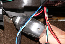
 With a hole saw on a power drill, I popped a 1/2"
hole through the firewall and added a grommet.
 |
| |
|
|

 The main power harness includes 14 gauge wire for the
12V Battery wire (red) and the Ground wire (black).
|
|

 I ran both through the firewall and into the motor compartment.
|
| |
|
|

 Next, I cleaned up a nice spot on the chassis to secure
the Ground wire.
|
|

 The 12V Battery wire must be fused. The SPAL FAN-PWM includes
and inline fuse holder and a selection of fuses. I used
the 30 amp fuse since that's what the Mark VIII fan pulls.
 |
| |
|
|

 After crimping the inline fuse holder to the 12V Battery
wire, I hooked it up directly to the positive terminal.
 |
|

 The Orange wire on the harness must be connected to a
12V Key-On source. The aftermarket Key-On terminal block
shown here was installed per the FordMuscle article...
Keen On 12 Volts Key-On. |
Getting
Power from the Controller to the Fan
The SPAL FAN-PWM has a dedicated harness than runs power from
the controller and to the fan. The harness uses a positive
(red) and negative wire (black). The Mark VIII fan has three
wires originating from the plug. Two are postive leads and
one is ground. As shown in caption 1 below, the blue wire
and the center black wire are the positive leads. When used
in its stock application, the positive black lead actuates
the fan based on engine temperature and the blue wire actuates
the fan when the air conditioning is turned on. Either positive
lead can be used with the SPAL controller. I chose to use
the blue wire. The center black wire was cut and sealed off
with shrink tubing.

 Here's a shot of the back of the fan showing the factory
plug and markings. I did not use the positive black wire
in the center.
 |
|

 The fan harness has a plug that is designed to connect
to a SPAL brand electric fan. It needed to be removed.
 |
| |
|
|

 Pretty simple, I ran the fan harness through the firewall
and along the intake.
 |
|

 The SPAL kit included heavy-duty connectors.
 |
| |
|
|

 After crimping, I bound the wires with electrical tape.
|
|
|
Connecting
the Temperature Sensor
As I mentioned earlier, the SPAL controller bases fan speed
on water temperature. The kit includes two harnesses. One
for a SPAL sensor (optional) and one for a use with an existing
factory sensor.
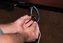
 I connected the supplied "OEM" sensor harness
(white) to the controller and ran it through the firewall.
 |
|
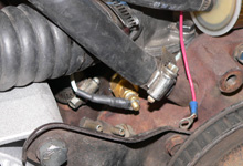
 The "OEM" sensor harness (white) works with
aftermarket gauge sensors too. The brass sensor shown
here feeds an Autometer electric water temperature gauge
(red).
 |
Installing
a Fan Override Switch
The SPAL FAN-PWM includes an AC harness to allow the fan to
come on full speed when the air conditioning is activated.
Since the 1972 Montego I was working on did not have AC, I
used the AC harness to connect to a toggle. This would allow
me to run the fan with the motor off.
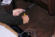
 The blue wire shown is used to connect to the "accessory"
terminal on a toggle switch. The gray wire was removed
since it is designed to serve a secondary fan.
 |
|

 To get power to the toggle I ran a 12V Key-On wire from
my terminal block. See the FordMuscle article...
Keen On 12 Volts Key-On. |
| |
|
|
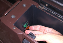
 After mounting and grounding the toggle switch (orange)
I got power to the fan. It was great to hear that thing
spin. See video in page one sidebar.
 |
|
|
|

